Metallurgical equipment
Helvess Limited Company is able to develop, provide and implement innovative technologies of global manufacturers of metallurgical equipment.

Slitting line 1,5-6,0X1500 mm
I. Material parameters
Technical characteristics
1. Material: hot-rolled steel, cold-rolled steel (St.2, St.3);
2. Thickness: 1,5-6,0 mm;
3. Width: max. 1500 mm;
4. Inner diameter: ∅458- ∅508 mm, ∅560- ∅610 mm, ∅710- ∅760 mm;
5. Outer diameter: ∅1000- ∅2000 mm;
6. Maximum carrying capacity: 15000 kg.
II. General data about equipment
1. Power supply: AC380V±10%/ 50 Hz, (or according to Buyer’s requirements);
2. Capacity: 250 kW;
3. Dimensions (L x W x H): 30 m x 8 m х 3 m;
4. Total weight: 70 tons. (approximately 4 x 40 HC containers are requested for transportation);
5. Operators number for 1 line: 3-5 workers;
6. Line color: according to Buyer’s requirements (as standard the casing is green, protected area is yellow);
7. Movement direction (uncoiling direction): according to Buyer’s requirements (as standard right to left).
III. Main components and operation process
Charging carriage > uncoiling machine > guiding device > hold-down roll of feeding device and straightening device from 5 rolls > crop shear at inlet > centering device > main slitting unit > scrap winder > buffer pit > pre-separation and tension > recoiler > discharge carriage
IV. Technical characteristics of the components
1. Charging carriage
a) Two coil holders;
b) Welded construction, 4 guiding rails, and hydraulic platform;
c) Hydraulic drive;
d) Distance of movement: 2000 mm, movement velocity: 8.5 m/min;
e) Hydraulic piston: ∅180 х 700 mm;
f) Lifting height: 700 mm;
g) Maximum carrying capacity: 15000 kg.
2. Bi-conic hydraulic uncoiling machine
a) Three stages: ∅458-O508 mm, ∅560- ∅610 mm, ∅710- ∅760 mm;
b) Two parts, moving lateral for coil clamping, extension type – inner;
c) Extension type: coil extension in radial direction by means of the hydraulic piston and inclined slanting crosshead;
d) Hydraulic cylinder of unclamping: ∅140 х 75 mm;
e) Hydraulic cylinder of movement: ∅125 х 900 mm;
f) Braking method: pneumatic brake;
g) Maximum carrying capacity: 15000 kg.
3. Guiding device
a) Guiding device: including idler roll, hold-down roll and stripping device, mainly assists the uncoiling process and transfers the coil to the next process, the guiding roll opens the coils, hold-down roll unbends the coil head part, stripping devise supports and moves the steel sheets;
b) Idler roll: welded construction, hoisted by hydraulic, installed on the upper part of uncoiling machine;
c) Hoisting hydraulic cylinder: ∅100 х 500 mm, 2 sets;
d) Idler roll: ∅250 х 400 mm;
e) Motor: 4 kW;
f) Cylinder of the hold-down roll: ∅80 х 400 mm;
g) Stripping device construction: big guiding frame makes the hoisting, small guiding bar makes the stretching;
h) Stripping device hoisting: hydraulic cylinder ∅100 х 400 mm;
i) Stripping device tensioning: ∅63 х 400 mm.
4. Hold-down roll of feeding device + straightening device from 5 rolls
a) Feeding to hold-down roll and straightening with 3 rolls, main frame is a welded construction from sheet steel;
b) Feeding and straightening roll characteristics: ∅200 х 1600 mm;
c) Roll material: 40Cr, hardening HRC 55-56;
d) Hydraulic cylinder for hold-down roll gripping: ∅100 х 100 mm;
e) Straightening roll thrust: motor 2.2 kW with worm-gear reducer;
f) Feeding: A.C. motor 15 kW with converter and cardan joint.
5. Crop shear at inlet
a) Hydraulic cutting unit 6 х 1500 mm, 1 set;
b) Sheet head part cutting (is the head part is of bad quality).
6. Straightening and centering device
a) Construction: welded construction from steel sheet, vertical roll for limitation of positioning;
b) Vertical roll characteristics: ∅90 х 125 mm, 3 pairs, high-frequency current hardening;
c) Hold-down roll characteristics: ∅100 х 1600 mm;
d) Hydraulic piston: ∅80 х 100 mm for hold-down roll;
e) Straightening rate: screw spindles, manually operated, 300-1500 mm.
7. Main slitting unit
a) Shaft characteristics: ∅240 х 1600 mm (for blade installing);
b) Shaft material: 40Cr, hardening, hard chrome coating;
c) Circular blade characteristics: ∅360 х ∅240 х 10 mm;
d) Circular blade material: instrument steel, HRC58~60;
e) Longitudinal cutting width: min. 20 mm;
f) Motor capacity: D. C. motor 90 kW with reducer and spindle;
g) D.C. Motor control: Eurotherm 590;
h) Hold-down: motor 2.2 kW;
i) Blades changing method: one-side moving frame, hydraulic-actuated, hydraulic cylinder ∅63 х 900 mm;
j) Operation velocity: 0-80 m/min – adjustable.
8. Scrap winder
a) Dual-sided hydraulic drive of winder;
b) Winder coil characteristics: ∅450 х 350 mm;
c) Motor capacity: 4 kW for both sides separately, receiver control;
e) Carrying capacity: 1 ton.
9. Looper with looping pit
a) Construction: concrete pit, dual-sided reversible plate;
b) Pit dimensions: 4.5 m x 2.0 m x 3.5 m (at the cost of the Buyer);
c) Reversible plate construction: welded angle steel with sliding rolls on both ends, and the roll with coating from abrasion-resistant plastic;
d) Displaceable hydraulic piston: ∅80 х 500 mm.
10. Unit for pre-separation and tension
a) Pre-separation shaft size: ∅80 х 1600 mm;
b) Pre-separation plate size: ∅200 х 3 mm;
c) Pre-separation plate material: 65Mn, hardening;
e) Hydraulic cylinder for shaft hold-down: ∅75 х 100 mm, pressure adjustment;
f) Tension roll size: ∅200 х 1600 mm;
g) Tension roll material: 40Cr, heat treatment HRC 55-56;
h) Tension roll hold-down: hydraulic cylinder ∅100 х 100 mm, 2 sets.
11. Recoiler
a) Gearbox, hydraulic drive for clamping and unclamping, hydraulic cylinder ∅200 х 100 mm;
b) Coiling device supporting part: steel construction, hydraulic cylinder, ∅80 х 350 mm;
c) Motor capacity: D. C. motor 110 kW with reducer’
d) D.C. Motor control: Eurotherm 590;
e) Recoiler shaft characteristics: ∅230 х 1600 mm;
f) Size of recoiler crosshead: ∅508 х 1600 mm;
g) Pressure shaft characteristics: ∅95 х 1600 mm, hydraulic drive, hydraulic piston ∅80 х 350 mm to hold-down;
h) Separating plate size: ∅200 х 3 mm;
i) Separating plate material: 65Mn, hardening;
j) Pushing power at discharge: hydraulic piston ∅80 х 1600 mm;
k) Speed of recoiling: 0-80 m/min, adjustable;
l) Maximum carrying capacity: 15000 kg.
12. Discharge carriage
a) Steel welded construction on four wheels;
b) Motor 3 kW;
c) Hydraulic cylinder ∅180 х 700 mm;
d) Maximum carrying capacity: 15000 kg.
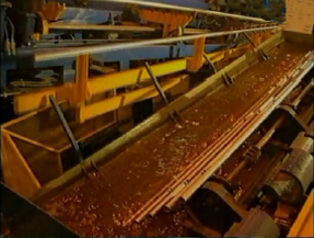
Pipe galvanizing line
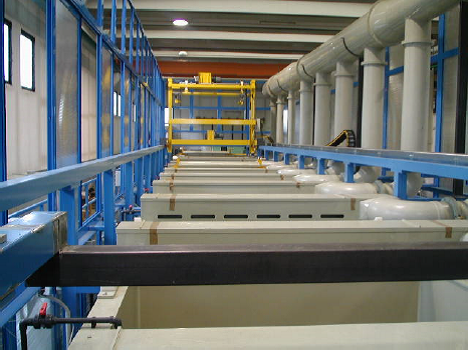
| Automatical pretreatment | The pipes are fed in packages from the warehouse to the loading table by the fork lifter. Operator leaves the package on the loading table and presses the button. The pipes are automatically fed to the starting point of the line inside the casing. Special crane picks up the package and drops it into the first pretreatment bath, and then the pipes are pretreated under the control of the software. After this process, the package remains on the table coming out of the casing and each pipe is prepared for feeding into the dryer. |
 |
|
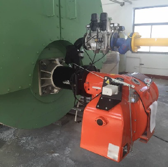
| Dryer | The pipes are fed into the dryer automatically. The hot air from the furnace is used in the dryer. An auxiliary burner is also switched on in case of temperature drop. All pipes are heated up to 100°C to prepare them for dipping into the zinc melt. |
| Two sided roller table | After the preheating furnace, the pipes are placed, one at a time, on a double-sided roller table system. The pipes move on along an inclined line and are discharged into the zinc bath. A roller table is a system of powered rollers. Some rollers are magnetized, to ensure smooth feeding of pipes. The roller system is driven by an AC motor with a speed inverter, allowing the speed to be adjusted to suit the diameter of processed pipes. |
| Zinc bath | Metal sheet thickness: 50mm Inner dimensions: 8,5×2,0x3,0 m Total weight: 34,000 kg |
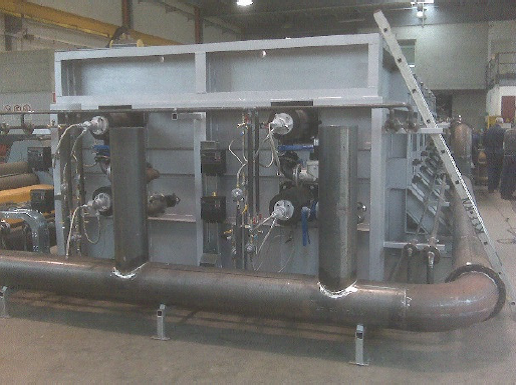
| Hot dip galvanizing furnace | It is a hot-dip galvanizing furnace with an on/off ignition system, with heat insulation and self-contained hydrostatic head support system. Special heat distribution inside the furnace ensures a significant difference in zinc melt temperatures in upper and lower parts of the furnace, and also 10°C lower at the production stage. Thus, a lower temperature at the bottom of the bath ensures several important advantages: The burning system is divided into 4 different areas with independent control. Each burner can also be switched on separately, so that all the burners are not used at once. The conditions of pressure reduction, neutrality and boost, that shall be set inside the heating chamber are kept automatically by coefficients at all stages of burning due to a proportional throttle lock installed on the exit gas duct and monitored by a pressure sensor. The furnace is designed with a capacity of 16 t/h. |
 |
|
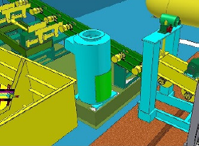
| System of pipe submergence into zinc bath | The system consists of support beams that are placed on the furnace foundation. The dipping system of special design ensures a quick change of the pipe diameter. The roller table, which is an extension of the one described above, is mounted on a shaft driven by a cylinder that moves the rollers so that the pipe is on three wheels. |
| Pipe extraction system | The automatic extraction system consists of a permanent roller-type magnet and non-magnetic rollers. The roller system for pipe extraction consists of 4 bigger diameter magnetic rollers supporting the pipe along the lower generating line and a set of smaller diameter magnetic and non-magnetic rollers supporting the pipe along the entire upper generating line. The AC motor-driven magnetic rollers with speed inverter are independent, so the pipe extraction speed can be adjusted for each diameter of the processed pipes. |
 |
|
| Internal and external cleaning | The pipe passes along the rollers through a ring with a rim of holes. Compressed air is supplied through these holes to remove excess zinc from the outer surface of the pipes. The pipe is automatically extracted from the zinc bath, placed in contact with the first magnetic roller, and continues its movement along the extraction route up to the electric regulator. Once switched on, it sets a mechanical conveying device in motion that automatically delivers the pipe to the blowing station. At the blowing station, the pipe is stopped by a pneumatic clamp, and then the steam supply valve is lifted to the end of the pipe, automatically opened by the pressure of the pipe, then supplies the steam necessary to remove excess zinc from the inner walls of the pipes. Then the valve moves backwards, stops steam supply, and the clamp releases the pipe. The pipe is moved by the conveying device, described above, to the mechanical elevator of pneumatic action. The pipe is brought to the level position and sent to the cooling bath. The blowing station cart is designed to supply steam to clean the inner side of the pipe at two different stations according to the required degree of coverage. The same cart is also equipped with a motor to stop at a specific location as per the length of the pipe. |
 |
|
| Cooling bath | From the passivation bath and cooling bath, into which cold water and/or passivating solution are fed, the pipe is pushed by a group of chains with a drive and toothed brake. The chains move at intervals, one per pipe ensuring an excellent synchronization between pipes and chains while simultaneously removing any water remaining in the pipes. |
 |
|
| Steam generator | The steam required for blowing and cleaning the inner surface of the pipes after galvanizing is supplied by a special system. This system consists of an artificial ionic water softener to produce pure water which is suitable for steam generation. The water is stored in 15m3 polyethylene tanks and further used in a steam generator with a capacity of approx. 1,300,000 kCal/h. Steam is generated through the insulated piping at a temperature of approx. 220-240°C under 5 bar. The delivery includes a CE certified TSS72 SAFETY SYSTEM suitable for 72 hours of operation without operator supervision. |
 |
|
| Zinc collection unit | Steam blast of the pipes creates effluent waters from water vapor and metallic zinc dust. These effluents are collected and piped to a scrubber. For example, a water scrubber from steel, divided into two independent stages to clean the contaminated air. |
 |
|
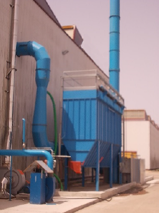
| White smoke cleaning device | The fume generated while dipping pipes into the zinc bath is collected and routed through a pipeline to a dry filter with a capacity of approx. 20,000 m3/h for dust cleaning, equipped with an automatic compressed air cleaning system and a system for material discharge. The structure consists of galvanized 20/10 moulded panels which ensure perfect wear resistance and high level of strength. The filter hoses are mounted on the baskets from galvanized steel wire. |
 |
|
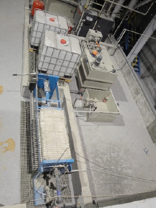
| Treatment with flux | This unit consists of a box with special pumps and a hydrogen ion exponent control system, including electronic monitoring, a three-way valve for passage selection and a probe with a Ph electrode. A 1m3 tank for storing ammonia agent and hydrogen peroxide, complete with level switches, ventilation and auxiliary accessories. Filter press 500x500mm with 25 plates, hydraulic closure and manual carriage and a feeding pump driven by an engine. Pipes, fittings, valves made of durable PVC to connect to the unit complete with clamps and leveling units. |
 |
Round pipes maximum capacity
| Nominal size | Pipe weight | Capacity | ||
|---|---|---|---|---|
| inch | kg/m | Kg/6.0m | Pcs./h, ca. | kg/h, ca. |
| 1/2” | 1.22 | 7.32 | 900 | 6500 |
| 3/4” | 1.58 | 9.48 | 900 | 8500 |
| 1” | 2.44 | 14.64 | 900 | 13100 |
| 1”-1/4” | 3.14 | 18.84 | 900 | 16000 |
| 1”-1/2” | 3.61 | 21.65 | 900 | 19000 |
| 2” | 5.20 | 31.2 | 770 | 24000 |
| 2”-1/2” | 6.68 | 40.08 | 600 | 24000 |
| 3” | 8.37 | 50.22 | 480 | 24000 |
| 4” | 12.15 | 72.90 | 330 | 24000 |
| 5” | 16.64 | 99.84 | 240 | 24000 |
| 6” | 23.52 | 141.12 | 170 | 24000 |
Square and rectangular pipes maximum capacity
| Pipe dimension/mm | Pipe weight | Capacity | |
|---|---|---|---|
| Kg/6 m | Pcs./h | Mt/h | |
| Square pipe | |||
| 25x25mm | 9.42kg | 720 | 6.782 |
| 30x30mm | 11.3kg | 720 | 8.136 |
| 40x40mm | 15.07kg | 720 | 11.85 |
| 50x50mm | 23.55kg | 720 | 16.956 |
| 60x60mm | 33.912kg | 600 | 20.347 |
| 80x80mm | 52.75kg | 300 | 15.825 |
| 100x100mm | 56.52kg | 300 | 16.756 |
| 120x120mm | 90.43kg | 240 | 21.703 |
| Pipe dimension /mm | Pipe weight | Capacity | |
| Kg/6 m | Pcs./h | Mt/h | |
| Rectangular pipe | |||
| 20x40mm | 11.3kg | 360 | 4.064 |
| 25x50mm | 14.3kg | 360 | 5.148 |
| 30x60mm | 21.19kg | 360 | 7.628 |
| 40x60mm | 23.55kg | 360 | 8.478 |
| 50x80mm | 36.74kg | 360 | 13.226 |
| 60x100mm | 45.21kg | 360 | 16.275 |
| 80x120mm | 75.36kg | 300 | 22.608 |
| 100x150mm | 94.2kg | 240 | 22.608 |
Throughfeed type shot blasting machine with roller tables
| 1 | Workpiece max dimensions | 12500mm*427mm (length*diameter) |
| 2 | Unit bore dimensions | 1000mm*550mm (width*height) |
| 3 | Roller table load | ≤500 kg/m |
| 4 | Roller table travelling speed | 0~0.4 m/min (Frequency control) |
| 5 | Shot blast speed | 0.8~1.2 m/min (Frequency control) |
| 6 | Rust removal quality class | GB8923/88 A/B Sa2.0-Sa3.0 |
| 7 | Abrasers | 0.8~1.2 (cast or pelletized steel shot) |
| 8 | Noise level | ≤92 dB, acc. to GBJ87-85 standard |
| 9 | Emissions | ≤30 mg/m3, acc. To GBJ4-73 standard |
| 10 | Harmful substances content in the working area | acc. to TJ36-79 standard |
| 11 | General ventilation | approx. 10000 m3/h |
| 12 | Total power | approx. 70 kW |
| 13 | Total compressed air flow rate | 0.5-1.0 m3/min |
| 14 | Dimensions | Length: approx. 29900 mm |
| Width: approx. 5500 mm |
| Shot blasting machine | Blast wheel | Q-ty: 4 pcs |
| Shot blasting volume: 4*180 kg/min | ||
| Power: 4×11 kW | ||
| Bucket elevator | Lifting volume: 45 t/h | |
| Power: 4 kW | ||
| Separator | Separation volume: 45 t/h | |
| Power: 2.2 kW | ||
| Longitudinal conveyor | Transportation volume: 45 t/h | |
| Power: 2.2 kW | ||
| Cross conveyor | Transportation volume: 45 t/h | |
| Power: 2.2 kW | ||
| Grit controller | Pneumatic valve | |
| Max capacity: 400 kg/min | ||
| Blast cabinet | In the machining zone: rolled steel Mn13 protection plate, thickness 10 mm. Service life — over 13000 hours. | |
| Roller tables in chamber | Diameter*distance: Ø89х800mm | |
| Roller loads: ≤500 kg/m | ||
| Conveyor speed: 0~4 m/min | ||
| Speed control method: frequency converter |
Hot dip galvanizing line
(Capacity 700 tons)
Steel strips
| Coil material: | St.1, St.3 |
Hot-rolled steel with oxides in the form of Fe203, FeO, Fe304 compounds on the surface (before the etching process)
| Coil thickness: | 4-5 mm |
| Coil width: | 240 mm and 300 mm (in the slitting line up to six 40 and 50 mm strips) |
| Number of passes of strips: | 6 strips at the same time |
| Inner diameter of the coil: | 508 mm |
| Outer diameter of the coil: | ≤1800 mm |
| Coil weight: | ≤5 ton |
Bars
| Material of bars: | St.1, St.3 |
Hot-rolled steel with Fe2O3, FeO, Fe3O4 on the surface (before the etching process)
Stretched wire without iron oxide on the surface, preservative lubricant used in the drawing process: NaOH, GaOH, C16H32O2, animal fat, vegetable oil, paraffin, technical soap, talcum powder powder, industrial alkalis, etc. are included in the removal process.
| Diameter of bars: | 6 / 8 / 10 / 12 mm |
| Passage of bars: | 6 bars at the same time |
| Inner diameter of the bar: | 700 — 850 mm |
| Outer diameter of the bar: | ≤1300 mm |
| Final width of the coil: | 40/50 mm |
| Final thickness of the coil: | 4/5 mm |
| Final zinc surface density: | 45 g/m2 — 275 g/m2 |
| Final inner diameter of the coil | 508 mm |
| Final outer diameter of the coil: | 1000 mm |
| Final diameter of the bar: | 6 / 8 / 10 / 12 mm |
| Final zinc surface density: | 60 g/m2 — 275 g/m2 |
| Final inner diameter of the bar: | 508 mm |
| Final outer diameter of the bar: | 900 mm |
| Production volume: | 6 pcs |
| Capacity: | 10 tons/h |
| The galvanizing process of bars and coils takes place on the same line. | |
| Name | Q-ty of sets |
| 1. Coil handling car | 2 |
| 2. Uncoiler | 2 |
| 3. Gripping and guiding device | 1 |
| 4. Automatic welding machine | 1 |
| 5. Deoxidizing system | 1 |
| 6. Hardening machine, first | 1 |
| 7. Accumulating device | 1 |
| 8. Slitting machine | 1 |
| 9. Stretch test system | 1 |
| 10. Heating room | 1 |
| 11. Cooling device | 1 |
| 12. Centering roller | 1 |
| 13. Galvanizing bath | 1 |
| 14. Lifting system | 1 |
| 15. Coiling system | 1 |
| 16. Water cooling system | 1 |
| 17. Hardening machine, second | 1 |
| 18. Passivation system | 1 |
| 19. Loop unloading device | 6 |
| 20. Hardening machine, third | 6 |
| 21. Guiding device | 6 |
| 22. Recoiler | 6 |
| 23. Car for unloading of coils | 6 |
| 24. Bar unloading device | 6 |
| 25. Bar deoxidizing system | 6 |
| 26. Bar centering roller | 6 |
| 27. Automatic butt welding machine for bars | 2 |
| 28. Control equipment | 3 |
| 29. Hydraulic station | 3 |
| 30. Electrical control system | 1 |